Bikes are one of my favorite things, so when I got to choose an FEM final project I knew exactly what I wanted to do. I wanted to compare two of the most common materials in the cycling industry, aluminum and carbon fiber. Everyone knows marketing is the enemy of science and engineering so I wanted to quantify the benefits of a carbon fiber bike crank aside from "26.7% improved performance!" To perform this analysis I used ABAQUS student edition. To preface the results it should be noted that the student license of ABAQUS is limited to 1000 nodes, which is not a lot. This resulted in various simplifications throughout the analysis to meet the node count.
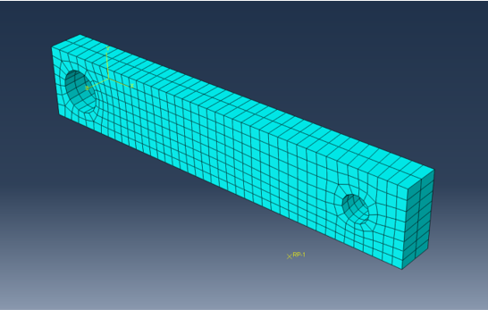
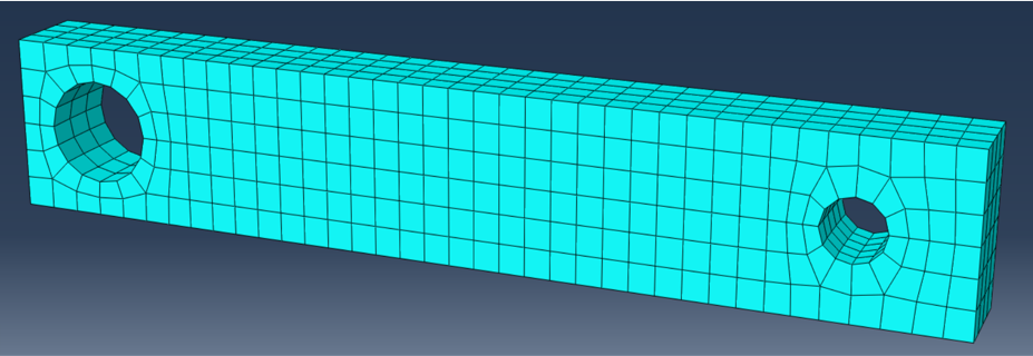
The first challenge to meeting the node count was the geometry of the crank. I decided to use a constant rectangular cross section with holes cut for the crank spindle and pedal axle. No curves aside from the holes were used because obtaining mesh refinement using tetrahedral or quadratic elements required too many nodes. I also ran two sets of simulations, one set using symmetry and half of the crank model, the other set using a full crank.
The next challenge was determining the most accurate boundary conditions. I chose to fix the surface that would be in contact with the crank spindle and apply forces to a reference point which acted as the "pedal" for the simulation. For the set of simulations utilizing symmetry, the appropriate symmetry boundary conditions were included on the back edges of the crank.

Half crank mesh
The last challenge was applying the material data for carbon fiber. To apply the material the engineering constants for a prepreg using Toray T700G fibers was used. These values were found from two studies that evaluated the material. Although different resins were used the values were similar and the lower values were between the two studies was used as a safety precaution. To determine an accurate force magnitude empirical data from academic studies were used. A force was applied vertically and in the axial direction to represent two different possible loading scenarios. The results from the simulation along with more detailed explanation can be seen in the full report which is linked below.

Full crank meshed

boundary conditions
Aluminum deflection plots
Carbon deflection plots